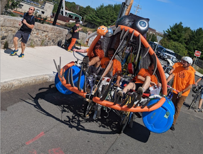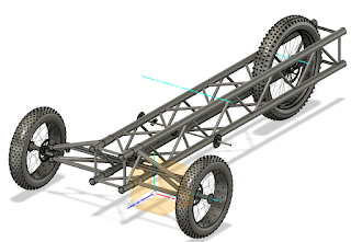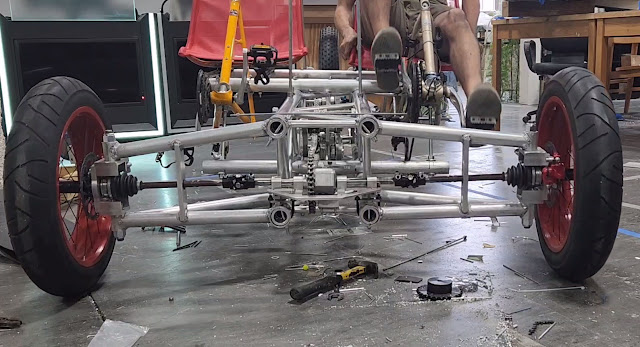
Pedals are mounted. Freewheels have been coupled to the Hyperdrive. Chains are connected. The Falcon can finally travel without being pushed. Huzzah!

It took some effort to get this far. After basking in the afterglow of mounting all the wheels, I got to work attaching the frames for the pedals. We are going to pedal recumbently but we are using regular mountain bike frames. I mounted them at an angle like they are “popping wheelies,” so that the pedals can be cranked from a seated position. The freewheels they turn are located under the drivers’ seats and line up with the input shaft of the Hyperdrive.


The bike frames had to be secured to the truss but the support structure also had to clear the path of the pedals. At first I thought I’d have to weld some tubing together at eccentric angles and drill holes in the bike frame to attach, but after staring at it for a while an easier solution presented itself that didn’t require any welding or virtual development. Who needs Fusion 360 to engineer parts? I do, but in this case I was able to make all the modifications IRL.
I bolted a single aluminum tube with 1/4 inch thick walls across the truss, much like the support tubes for the seats. Then, I bolted 1/2 inch threaded rod between the support tube and the kickstand bracket(!) on the bike frame. Only one of the frames had a kickstand bracket, so I used fender washers as a makeshift bracket for the other one.

Not only was welding not necessary, but the height of the pedals are now adjustable. The rear forks were secured to the front seat support tube using hose clamps.

I then mounted all the bike hardware onto the bike frames. This was the easiest way to see what was missing and what needed to be replaced. The pedals rubbed up against one of the bike frames, so we had to get a slightly wider bottom crank. We also needed a different front derailleur and a new set of gear shifters.
Alternative Freewheel Support
Normally, the rear hub of a bicycle spins independently of the axle bolt that attaches the wheel to the bike. However, the Falcon needs the freewheels to do the opposite, to actually turn the axles. They make adapters that do this, but a spinning axle meant we had to mount bearings somewhere to support them. And the bearings also needed to be close enough to the freewheels’ original location so that we could still run bike chain from the hub and derailleur to the pedals. To accomplish this I had to design a new part that sits the the elbow of the rear fork.

I designed it so it can be bolted to the rear forks using the original hub location’s bracket holes. Before making this part in metal, I 3D printed it in plastic. Good thing, too, because the initial design fit on one bike frame but not the other. I figured out that I could make it work by stretching the mounting hole into a slot (see image above).

Once I updated the part virtually, I made the brackets on the Tormach CNC mill.


The new location of the freewheel works great! The only issue is we can’t go down to its smallest gear or the chain rubs against the bolt securing the bracket. I just set the limits on rear derailleur to avoid that gear.

Drive Sprockets


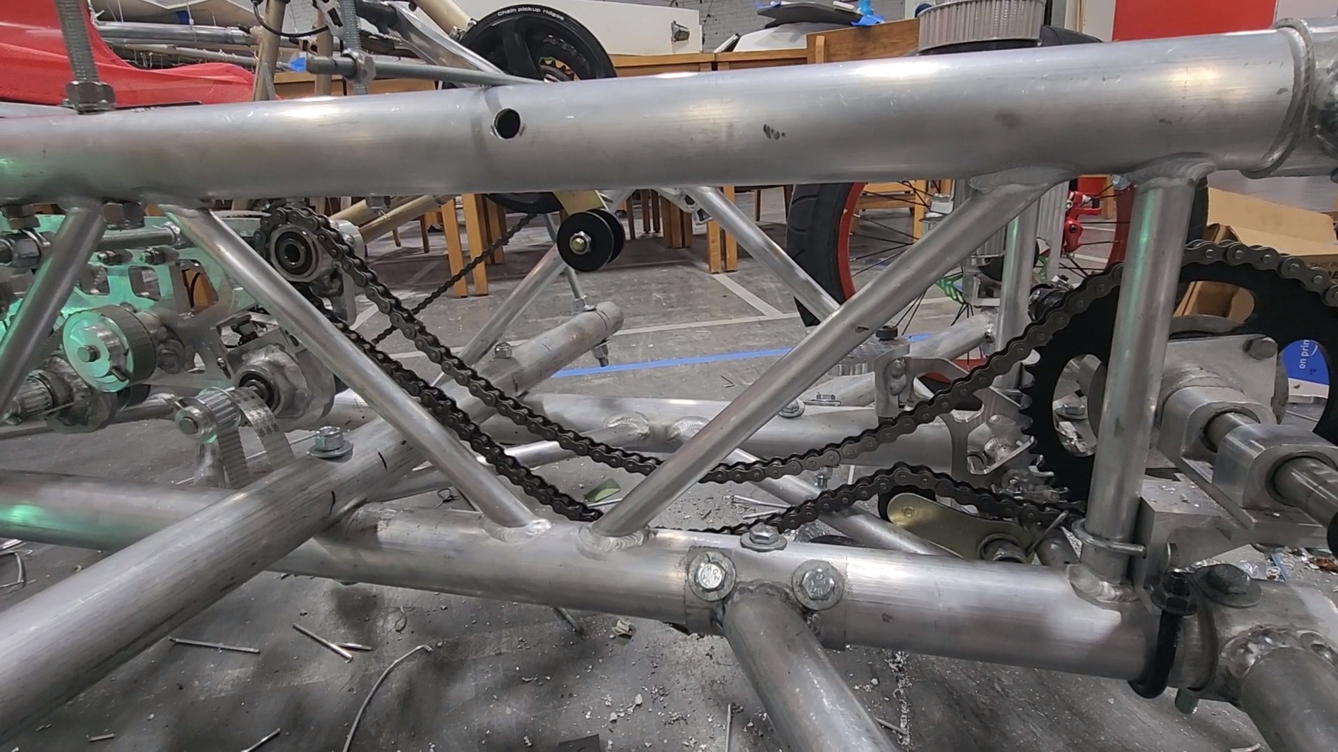

I put the Hyperdrive back together and tried the pedals a third time.

We still have to mount the rear drive sprocket and chain, work out the rest of the steering mechanism, make a brake lever, run the brake lines to the lever, add flotation and turn the front wheels into paddlewheels. No sweat (i.e., multiple long days of sweat).