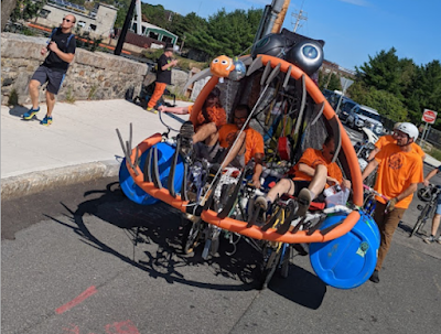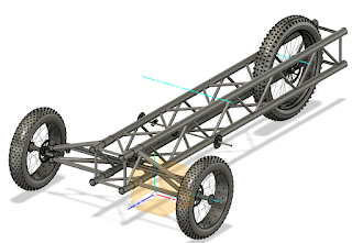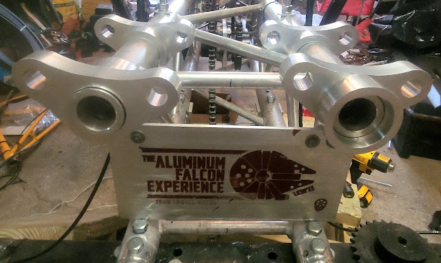
Fabrication of the new suspension continues. I made the last of the hanger brackets, so we can now officially attach the new suspension to the Falcon!


I also made the next four parts in the build: the alignment bracket that keep the hangers and the suspension arms in the same position, relative to each other.
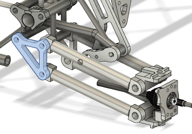
These were deceptively difficult to make. First, because of their size, I had to hold them in the machine differently than usual. That wasn’t too bad. I just moved the jaw bolted to the front of the movable block on the vice, onto the rear position.


Carving out the first side of the part went well. I like to call this the “Han in carbonite” phase.

I was able to remove all of the interior material without cutting through the bottom of the stock plate. The stock I used is 3/4 inches thick and the bracket is .7 inches thick. That 0.050 difference made sure I didn’t accidentally cut into the vice. Because the vice jaws were in the way, I couldn’t cut along the outside of the part. That left the bottom .25 inch thickness of material to avoid that.
I usually just flip the part over and remove the “carbonite” layer to finish the part, but since I need to maintain bracket thickness I also had to precisely trace the outline of the part from the other side. That’s why there was one hole cut all the way through the first side. That hole became the origin for all the flip side operations.

I began finishing the second side by manually cutting away most of the extra material using a bandsaw. It didn’t take very long and helped reduce CNC machining time.

Because the part is triangular, I had originally planned to hold it along the hypotenuse but that wasn’t possible. In that orientation, the part is not wide enough for the vice to hold it. And, yes, it was also too wide to move the vice jaws back. smh
I was stuck. To finish the part, I needed to make a custom jig–a part to finish the parts. If I could clamp the jig in the vice I could then secure the triangular brackets to the jig. I began with a 6 inch by 6 inch stock plate and designed the jig to use the central trapezoidal shape of the part to keep each bracket from shifting or rotating. I added 1/2″ threads so I could lock each part down onto the jig with bolts.


Using bolts on the inside of the part meant that I couldn’t use the Tormach to finish the back face of the bracket, so I did it manually. I had to keep the face mill moving to avoid tool marks. It reminded me a bit of playing the drums.


Once the jig was complete, I slipped each faced bracket on, bolted it down, and cleaned up the outlines.


The jig made easy work of finishing the alignment brackets.

With these parts, we are 50% through the build!

Next up, the parts that attach the wheel to the suspension and all the remaining steel structural pieces. For the glory!