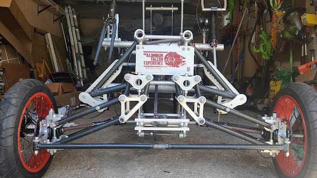
We’ve been trying to get to our first v3 road test for a month. Timing and complications have drawn out the effort so far. We’ve installed the new front suspension, remounted the front tires, and reconnected all the inputs and outputs to the Hyperdrive (the main drivetrain). We only needed to finalize steering and connect the brakes to get to our first road test. Without them, the Falcon would be more runaway train than racecar.

I Brake for Kinetic Sculptures
We use bicycle brake discs and calipers on the Falcon. They are meant to install only on the right side of a bike, so using them on the left side of the sculpture created placement issues. We dealt with this last year by mounting one caliper behind the tire and the other in front of the tire. The new suspension required that both calipers be located behind the wheels. I thought I would need to make a special bracket for the left side wheel, but it dawned on me that I could actually still use the same bracket…if I installed it upside down. Both calipers were behind the tire, the left side below the axle and the right side above it.


To solve our race killing problem from last year, we had added a lip to the outside of the plates to keep the bearings from squeezing out.


This made the plates thicker overall and moved the calipers too close to the brake disc. I thinned the mounting tab to move the caliper inward a bit and aligned the calipers with the brakes discs.

I originally wanted to be able to activate all the brake calipers using a single handlebar brake. As with everything else on this beast, doing this required some engineering. I designed and fabricated a small manifold that would tie all the brake lines into a common bar that slid back and forth in a slot.

I then attached the brake line for the handle to the common bar in the manifold, looping the cable tightly enough so that squeezing the brake handle would pull the bar back, which would then pull on the caliper arms and activate all the brakes simultaneously.

This did not work at all. There was not enough leverage at the handle to fully activate the brakes. I went back to the central brake lever idea from last year, so we could get testing.

Need More Direction
We could now stop and that was very important! Next, we needed steering. My steering schemes had not worked very well so far. I first tried a vertical swing arm. It was way too short and did not generate enough force to turn the wheels without great difficulty. I switched to a horizontal swing arm for the second attempt. It worked better, but not by much. I tried getting more leverage by using a longer steering arm, but to do that, I had to reposition the steering arm so it swung in clockwise, from the outside. However, that reversed everything–pulling left steered right and vice versa. I had to install gears to reverse the direction, but that system was never stiff enough to be effective.

In the latest design, I kept the same basic idea from the second attempt, except the gears. We also switched from a steering wheel back to bicycle handlebars. Handlebars made more sense since we were using full bike frames for the pilots. Turning the handlebars would spin a horizontal swing arm that would then push/pull an arm attached to the front wheel (the pitman arm) and turn it in the correct direction. I converted the front fork of the new bike frame into a new steering column, cutting off the legs of the fork and pinning a 3/4 inch shaft to the remaining structure.


The bike’s head tube secured the steering column at one end, but the bottom also needed to be held in place. I brought back the support bar that I had used with the previous steering scheme. The installed support bar was not quite in the right spot to receive the steering column pivot point, so I designed and fabricated a ledge plate to brace the steering column at the correct location.

After attaching the swing arm to the steering column, I just needed to connect it to the pitman arm attached to the wheel. This was the final design challenge around steering. The wheels were capable of dropping almost 4 inches in relation to the steering swing arm. I needed something that would not only transfer the turning force of steering arm to the wheel, but also slide up and down somehow.
After a few iterations, I settled on a hinged, C-shaped transition arm. I made the arms using the Tormach and then welded all the pieces together.